Floor Support Installation Instructions
1. ALWAYS store adjustable metal pins in a dry place.
2. Before final installation and/or when installing the support, lubricate the pin by applying a bead fo good quality grease extending the entire length of the pic. Screw the nut up and down the pin at least once to spread the grease evenly.
3. The PCO Adjustable Floor Support must not be installed in a strained, crooked or awkward position. This may harm the floor support or cause collapse and possible damage or injuries.
4. When putting pressure on the eight inch adjusting pin, it should not be extended over five inches.
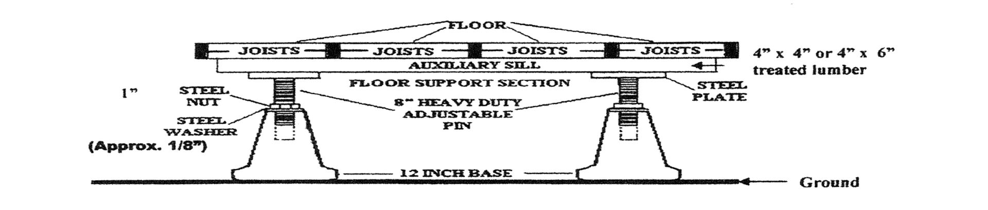
5. When installing the Floor Support on any application where a government inspection is required, mount the floor support on a concrete footing at least 16 by 16 by 8 inches deep, (18' by 18" if the unit is being installed beneath a 3 story building). Use 3000 PSI or better concrete mixture. If you have any questions, please contact your local authority.
6. At your option, you can attach the adjustable plate to the auxiliary sill or joist. We suggest using a 4x4 or 4x6 treated lumber sill attached to the plate with large screws. This product and instructions follow most government regulations. However, inquire with local building code inspectors if there is any doubt.
7. Adjustable Floor Supports are used primarily to support floors and to stabilize joist and sills. Caution: Be extra careful when using these supports under any load-bearing wall. Too much pressure may cause damage to the house structure.
8. Under un-cracked concrete and/or ceramic floors and/or concrete walls, the Adjustable Floor Support can be used for support only. The Floor Support is not designed for extreme upward movement.
9. We suggest using an Adjustable Floor Support every 4 linear feet.
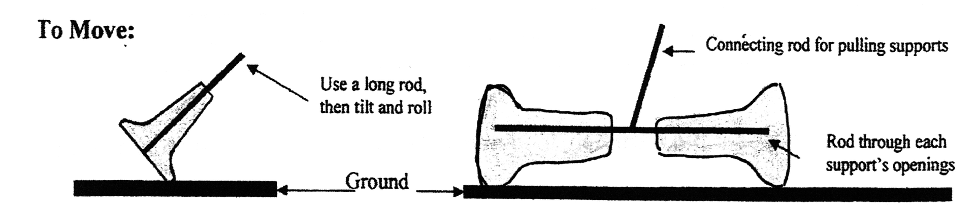
10. Inserting a long rod or stick in the top of the support and rolling the support on the edge of the base can easily move the Floor Support. Another suggested method of rolling two supports is to place a rod in each of the support's pin openings with another rod connecting the two at the center. The supports can then be easily rolled to their locations.